Solution 37798: What connection ports are available on the TI-Innovator™ Hub, and what can they connect to?
TI-Innovator™ Hub Port Information.
What connection ports are available on the TI-Innovator™ Hub, and what can they connect to?
3 input ports: Used to communicate and gather data from input modules:
- IN 1 and IN 2 are for 3.3V sensors. (most sensors are 3.3V sensors)
- IN 3 is for 5V sensors.
- Most sensors will work in any of the ports. (i.e., a 3.3V sensor will not get damaged if used with IN 3, but the readings may not be accurate)
3 output ports: Used to control output modules:
- OUT 1 and OUT 2 are for use with modules requiring 3.3V.
- OUT 3 is for use with modules requiring 5V, such as motors.

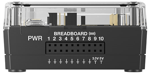
Breadboard connector: Twenty (20) receptacle pins for communication with components on a breadboard:
- The top row is for the signals and can be addressed in the programs using the “BB1..BB10” names.
- The first 8 pins on the bottom provide a ‘ground’ path for the circuit.
- The two other pins provide power – 3.3V and 5V.

I2C connector:
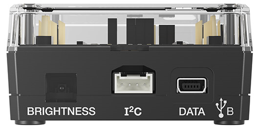
This port is for future capability, will connect to peripherals that use the I2C communication protocol.

What is the difference between the two USB ports?
DATA: This is a mini-USB port, labeled “DATA B”, that is used to connect to the TI graphing calculator, or a computer running TI-Nspire™ CX software. The USB port is located on the same side as the Light Sensor.
POWER: This USB port, labeled “PWR,” is located on the same side as the Breadboard connector.
This is a micro-USB port that is used for two purposes:
1) Connect to external power source (TI Wall Adapter and TI-Innovator™ External Battery) when using components that require 5V (e.g.: motor).
2) Connect to computer USB port to update the TI-Innovator™ Sketch.
For more details, please refer to the TI-Innovator™ System eGuide.To access the eGuide, please click on [View]. If you require further assistance please contact TI-Cares for support at 1-866-846-2844 or Send us an E-Mail.
